
Engineering drawings are the graphical language of engineering design. They communicate shape, size, tolerances, surface finish, and manufacturing requirements. These drawings follow international standards like ISO 128 and national conventions to ensure clarity and accuracy in communication across global teams. In this paper, we will introduce the definition, purpose, types and application areas of engineering drawings, as well as the basic elements of engineering drawings, how to draw them, how to read them, and common problems and solutions.

Definition of Engineering Drawing
An engineering drawing is a detailed representation of a part or assembly that shows geometry, dimensions, and manufacturing information. It uses graphic symbols, annotations, and notes to convey all necessary design data to engineers, fabricators, machinists, and inspectors.
In technical projects, drawings serve as contracts between designers and manufacturers. They include views from multiple angles, dimensions and tolerances, materials, surface finish requirements, and production notes.
Purpose of Engineering Drawing
Engineering drawings serve several core purposes:
Visualization of Design Ideas
They convert conceptual designs into a visual and measurable format. Engineers can inspect and refine parts before fabrication begins, saving time and resources.
Universal Communication
Drawings use standardized symbols and formats so that engineers in different regions or companies can interpret them consistently. This shared language eliminates ambiguity and prevents errors in production.
Documentation and Traceability
Drawings record design intent and specifications permanently. They become part of quality assurance and compliance documentation, especially in regulated industries.
Manufacturing Guidance
Machine shops depend on drawings for dimensions, tolerances, surface finishes, and material notes. These details directly influence CNC machining, tooling, and final inspection processes.

Types of Engineering Drawings
By Purpose
Design drawings are used during the conceptual stage. They help engineers explore different ideas, visualize potential solutions, and validate functionality before committing to production. While they may not include every detail, they provide the creative foundation for further development.
Working drawings, by contrast, are finalized documents that guide actual production. They contain all the technical details, tolerances, and specifications needed to manufacture and inspect the part. These are the drawings machinists and inspectors depend on to ensure accuracy.
By Method
Hand drawings are traditional and are still valuable for quick sketches or early design brainstorming. They can be made with pencils, rulers, and compasses, offering flexibility without requiring software. However, they lack the precision and efficiency required for modern manufacturing.
Computer-aided drafting (CAD) is the dominant method today. Tools such as AutoCAD, SolidWorks, and CATIA allow engineers to create, revise, and share designs with speed and accuracy. CAD integrates with CNC machines, simulations, and quality software, making it essential in modern engineering.
By Projection
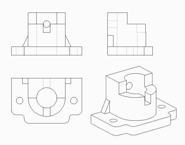
Orthographic projections show different views of an object, such as front, top, and side. They capture the exact dimensions without distortion, ensuring machinists can measure and produce components correctly. This method is widely adopted for technical clarity.
Axonometric or isometric projections provide a three-dimensional view on a two-dimensional sheet. They are especially useful for visualizing overall shapes and spatial relationships. While they may distort scale, they improve design communication for non-technical stakeholders.

Application fields of engineering drawings
Mechanical engineering
Mechanical engineering relies heavily on engineering drawings for part design, assembly instructions, and process diagrams. These drawings define dimensions, tolerances, and surface finishes, ensuring mechanical systems operate smoothly. Without them, machines would be prone to misalignment, inefficiency, and early failure.
Electrical engineering
Electrical engineering uses diagrams to represent circuits, wiring layouts, and control systems. Each symbol and line indicates connections, voltage ratings, and control logic. By following standardized electrical drawings, electricians and engineers can install and troubleshoot systems without confusion.
Civil engineering
Civil engineering depends on architectural plans, structural layouts, and construction drawings. These documents ensure that bridges, buildings, and infrastructure projects are built accurately according to design. Scale accuracy is especially important here, since even small errors can compromise structural integrity.
Chemical engineering
Chemical engineering applies drawings to represent process flows, piping layouts, and equipment connections. Diagrams help engineers visualize complex reactions, pressure systems, and separation processes. With them, safety and efficiency are maintained in industrial plants.
Other fields
Other fields such as aerospace, marine, automotive, and medical engineering also rely on precise technical drawings. Each industry adapts drawing conventions to suit its own requirements. For example, aerospace drawings emphasize lightweight materials and tight tolerances, while medical engineering focuses on biocompatibility and hygiene.

Key Elements of a Good Engineering Drawing
A clear and complete engineering drawing has these core elements:
Views and Projections
Multiple views reveal different sides of a part. Orthographic projections show accurate shapes and sizes, while isometric views help visualize complex forms.
Dimensioning and Scaling
Dimensions describe actual sizes. Scaling adjusts large objects to fit paper, while retaining proportional accuracy. Use consistent units (millimeters or inches).
Tolerances and GD&T
Tolerances tell how much variation is acceptable in manufacturing. Geometric Dimensioning & Tolerancing (GD&T) provides a symbolic language to control form, orientation, and location more precisely than traditional tolerances.
Examples include flatness, perpendicularity, and true position tolerances. GD&T symbols are defined in standards like ASME Y14.5.
Surface Finish
Surface finish symbols indicate roughness requirements; for example, Ra values define smoothness for functional surfaces.
Material and Treatment Notes
Drawings should specify materials and additional treatments like heat treatment, plating, or coatings.
Title Blocks and Notes
Title blocks hold meta information: part number, drawing scale, author, and revision history. Notes provide manufacturing and inspection instructions.
Drawing methods of engineering drawings
There are two methods of drawing engineering drawings, one is hand drawing and the other is computer-aided drawing.
Hand Drawing
The steps of hand drawing are as follows:
-
Prepare tools: Gather necessary tools like pencils, rulers, and compasses. Select the appropriate paper size and line types for the drawing.
-
Drawing frame: Use a ruler to draw a centered rectangular frame on the paper. Ensure the frame has even margins on all sides.
-
Drawing title bar: Create a small rectangle in the frame’s lower right corner for the title block. This area should contain key project information like the drawing name, scale, and author.
-
Drawing views: Select the correct projection method to draw the object’s views inside the frame. Arrange the views logically and scale them appropriately.
-
Drawing dimensions: Add dimension lines, symbols, and values to the views to indicate size. Place dimensions clearly without overlapping other lines and follow standard formatting.
-
Drawing symbols: Mark the drawing with standard symbols for materials, surfaces, or special features. Place these symbols close to the relevant parts and orient them correctly.
-
Checking and modification: Review the entire drawing for errors, accuracy, and clarity. Correct any mistakes by erasing and redrawing until the drawing meets all requirements.
Computer-aided drafting
The steps of computer-aided drafting are as follows:
-
Prepare the software: Install and set up CAD software like AutoCAD or SolidWorks. Familiarize yourself with the software’s interface and basic functions.
-
Create files: Start a new file and select the appropriate type, format, and drawing scale. Choose the correct units and precision for the project.
-
Drawing frame: Use drawing tools to create a rectangular frame on the page. This frame should be centered with even margins.
-
Drawing title bar: Draw a title block in the lower right corner of the frame. Use text tools to fill it with standard project information like the name, scale, and author.
-
Drawing views: Draw the object’s views inside the frame using lines, circles, and other tools. Arrange the views according to projection rules, either by drawing them directly or by generating them from a 3D model.
-
Drawing size annotation: Use dimensioning tools to add measurements to the views. Place dimensions clearly and format them according to standards, working from overall to detail.
-
Drawing symbols: Insert standard symbols for features like surfaces, welds, or threads. Place these symbols close to the relevant parts and orient them correctly.
-
Check and modify: Review the drawing for errors and inaccuracies. Use modification tools to delete, move, or adjust elements until the drawing is correct.
-
Save and Print: Save the file in the desired format and location. Print the drawing, ensuring the printer settings for scale and paper size produce a clear result.
Engineering Drawings in CNC Machining
CNC machining drawings translate design data into actionable instructions for machines. These drawings must include:
- Overall and detailed dimensions with clear tolerance callouts to ensure parts fit and function as intended.
- Surface finish symbols are needed for aesthetic and performance requirements.
- Material specifications guide tool selection and machining parameters.
- Use a single reference datum for positioning to avoid tolerance stacking. This ensures consistent results during CNC milling or turning.
Common Drawing Problems and Practical Solutions
Many issues arise from unclear drawings. Here’s how to avoid them:
- Ambiguous Symbols: Standardize symbols and educate teams on ISO or ASME conventions.
- Overcrowded Dimensions: Organize dimensions logically and remove redundancy.
- Scale Mismatches: Double-check that the title block scale matches the actual views.
- Missing Tolerances: Always include tolerances, especially for mating features.
Choose Richconn for Precision Engineering Drawings
When transforming a design into reality, choosing the right CNC machining partner is essential. Richconn specializes in precision CNC machining, prototyping, and manufacturing solutions. With deep expertise in engineering drawings, tolerances, and surface finishes, Richconn guarantees parts that meet exact requirements.
From prototype development to mass production, Richconn provides end-to-end services that include design consultation, production, and inspection. This ensures that every detail of your engineering drawing is respected during manufacturing.
For engineers who value accuracy, speed, and quality, Richconn is the trusted partner to bring designs to life.
Conclusion
Engineering drawings are the foundation of precise manufacturing and successful engineering projects. They express design intent, guide CNC machining, and ensure functional, high-quality parts. By following standards like ISO 128, ISO 2768, and ASME Y14.5, engineers and manufacturers can ensure consistency, clarity, and performance across global teams.
Clear drawings with proper dimensions, tolerances, surface finishes, and materials ensure efficient machining and reduce production costs. With good documentation practices and experienced partners like Richconn, your designs will become precision parts that meet exact requirements.
FAQ
What is the difference between design drawings and working drawings?
Design drawings are conceptual, while working drawings contain complete manufacturing details.
Why are section views important?
They reveal internal features that cannot be shown in external views.
What is the role of a title block?
It provides essential metadata—part name, material, scale, date, and drafter.
Why is CAD preferred over hand drawing today?
CAD offers higher precision, easy revisions, and compatibility with manufacturing software.
What industries rely heavily on engineering drawings?
Mechanical, civil, electrical, chemical, aerospace, and medical industries all depend on accurate technical drawings.